Concrete Condition Survey of
I-35 Northbound Overpass
IOWA DEPARTMENT OF TRANSPORTATION (IOWA DOT) | DES MOINES, IOWA, USA
The I-35 Northbound Overpass is a newly constructed flyover ramp connecting eastbound I-80 to northbound I-35 near Des Moines, Iowa. With a deck area of approximately 135,894 square feet, this overpass is a critical link in the state’s transportation network, supporting high volumes of interstate traffic. Ensuring its structural integrity from the outset was essential for safety, reliability, and long-term performance.
The Challenge
With the discovery of what appeared to be more cracking on the under-side of the deck as compared to the top side of the deck, Iowa DOT sought Niricson’s imagery in order to:
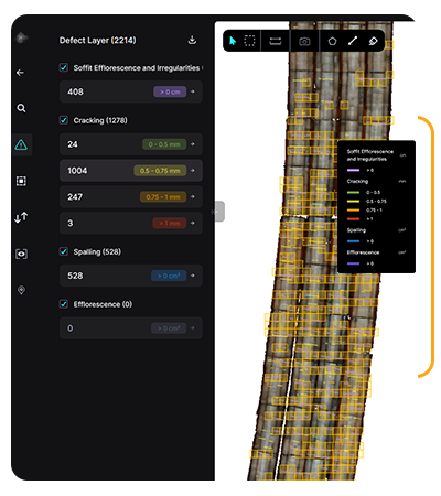
- Carefully document cracking location and sizes, for both the top and the bottom of the deck. Using the technology, we were able to get very precise location and crack width data.
- With the location and width data, we aim to compare the crack locations and sizes between the top and bottom of the deck.
The goal is to then potentially discern the initial starting point of the cracking in order to better understand the crack mechanism. We also plan to use the crack location and size data to continue to monitor the deck for additional cracking and crack size growth over time. Because, we have seen on other bridges that have demonstrated transverse cracking that some of the bridge decks have continued to develop new transverse cracking in subsequent years (up to 5 year) after deck placement.
Our Approach
Timeline
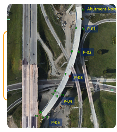
- August 2024 – Top deck survey of Units 2 & 3 (Niricson)
- October 2024 – Top deck survey of Unit 1 (Iowa State University drone team)
- December 2024 – Soffit survey (Niricson)
Technologies Used
- DRONIC™ (high-resolution data collection technology to map cracks down to 0.3mm)
- AUTOSPEX® (AI-driven defect detection and quantification platform)
- DJI M300 RTK drones with P1 sensor
- Canon EOS RP handheld camera with LED lighting solution for soffit collection
Execution
- Collected 0.5mm–0.7mm high-resolution RGB/optical imagery of both deck and soffit.
- Ground control points were established for accurate geo-referencing.
- Soffit data was captured using handheld methods and portable lighting due to restricted access.
- Data processed in AUTOSPEX®, enabling automated defect detection, quantification, and visualization.
- Results delivered through digital maps, defect overlays, orthoimages, and 3D models.
Results and Impact
Through this work, the team established a near time-of-discovery snap shot with respect to documenting the locations and widths of the cracks. The results provided an assessment if the concrete technology we employed for the last to be cast Unit 1 deck resulted in minimized crack size and frequency. Furthermore, with the top deck and soffit both captured, it allowed for the identification of “through” cracks together, from the top and bottom of deck scans and an understanding of any correlations between elements that cracked and the deck casting sequence as well as a comparison of cracking to restraining elements like the headed studs of the girders
For this project, it was absolutely crucial to capture the cracking in its very young age, within 2 to 3 months after casting, in order to also enable a design side analysis (which is about to start) of potential tensile strains developing in the top of the deck during casting of subsequent sections.


